 |
| |
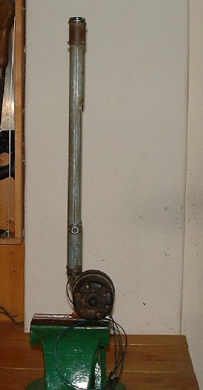
Rebuilding the Antenna...
Well... it didn't work, so that's another job that needs to be done
|
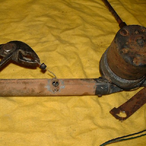
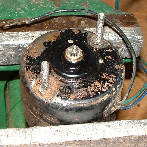
There were two different types of power antenna fitted to all 1959 and 1960 Cadillacs: Pioneer, and Tenna. This one is the Tenna type, and guess what...the manual says that the motor cannot be serviced, but I found a way. Actually, I bought this antenna really cheap on eBay - $5.99 - thanks to eBay Seller sho-mee81. I think the reason I got it at this price, was that the mast was snapped off near the base, and the motor didn't work. I wanted it because I like to tinker, and I was reasonably confident that I could do something with it. Click on the images to enlarge them, if you want to... |
||
|
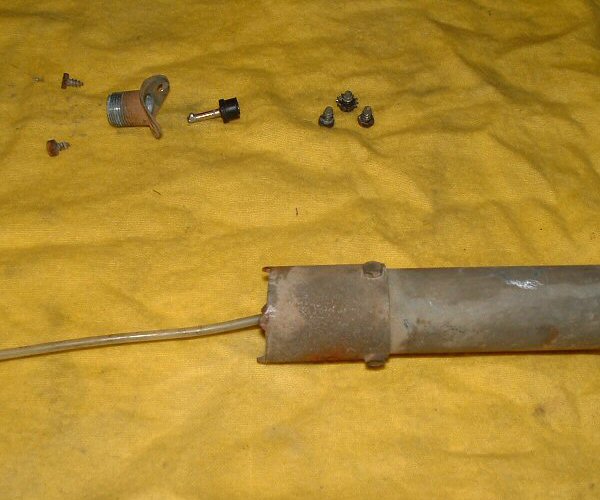
The first thing you need to do is remove the two screws and coax socket flange from the support tube, and then unsolder the hook-up wire from the pin and insulator, taking care not to melt the plastic. This will allow the support tube to be removed letting the wire slip through the hole. |

|
|
|
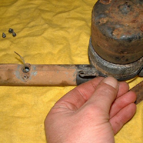
Remove the screws that secure the bottom part of the support tube to the drive assembly, and pull the earth wire free. While you are at it, you may as well undo the screws that hold the lower spacer on and remove it from the top of the support tube as well. |
|
|
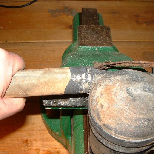
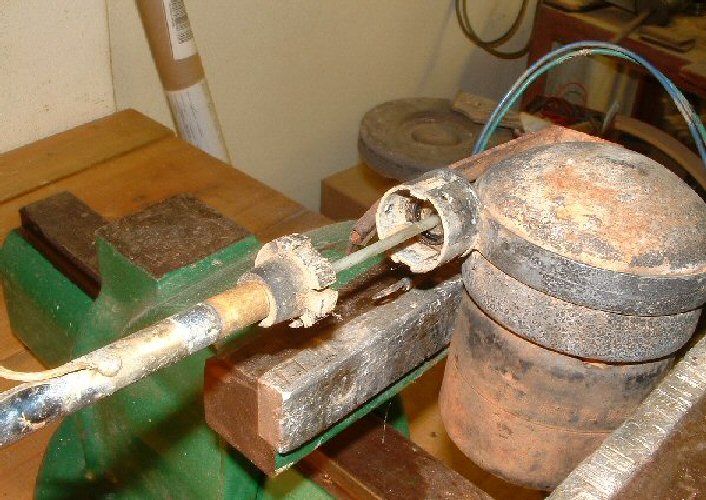
Next carefully clamp the motor in a vice taking care not to deform the motor casing, and pull the support tube free. With the support tube removed you can now pull the outer telescopic section of the mast assembly with the insulator bushing from the drive assembly. |
|
|
Had the motor been working it would have been possible to expel the nylon cord from the drive assembly by applying 12 volts D.C. to the appropriate power lead, but as the motor isn't working, this can't be done at this stage. |
||
|
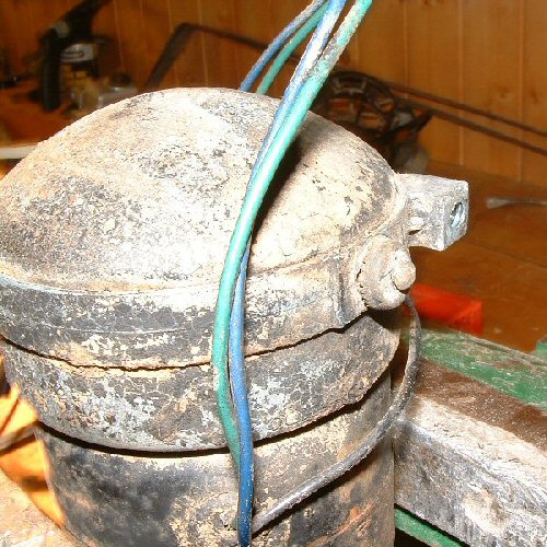
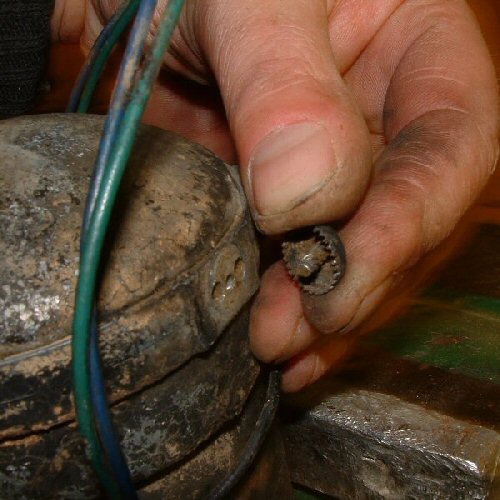
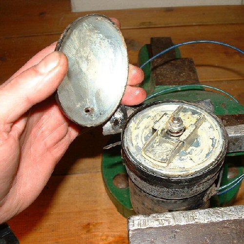
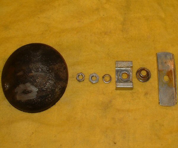
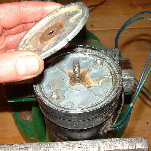
On the other side of the drive assembly is a small rivet and serrated domed washer, do your best to remove it at this point. Also remove the mounting bracket arm (not pictured here). |
|
|
|
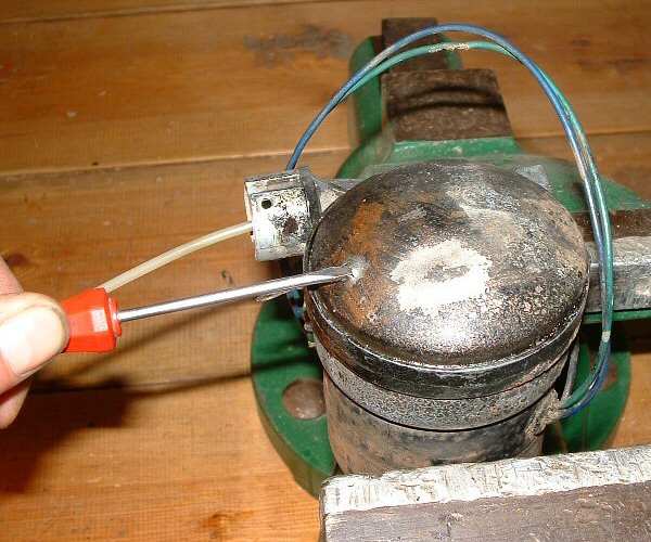
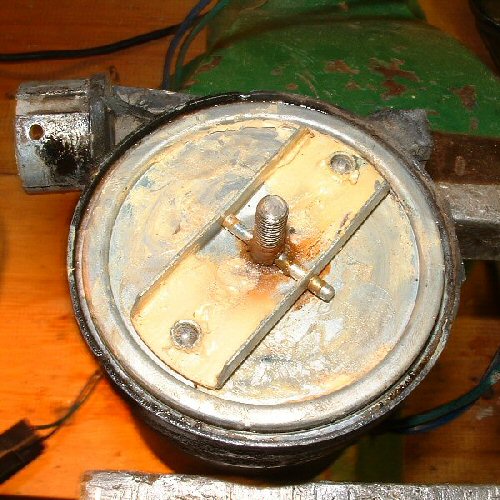
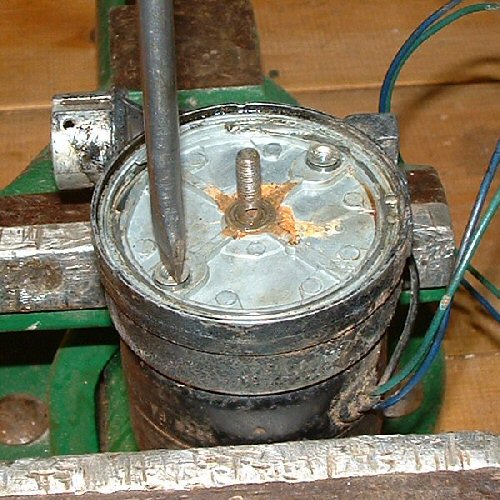
The drive assembly cover isn't really designed to be removed but there is a hole that a small screwdriver can be forced into and tapped upwards. With a bit of persuasion, and a spot of oil, the cover will come off. |
|
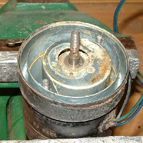
Remove these pieces and remember how they go back for later on. This is the mechanism that provides override when the mast is fully extended/retracted. Don't loose the two small ball bearings. |
||
|
|
|
|
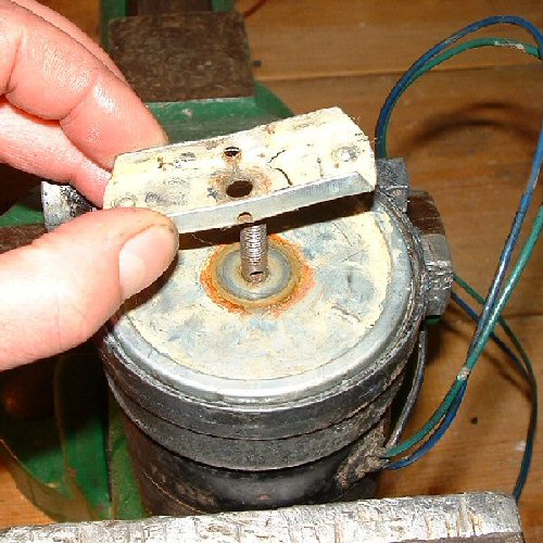
Lift off the cable winding top cover and remove the two screws that hold on the cable winding top housing and remove the housing from the remaining assembly. |
|
|
|
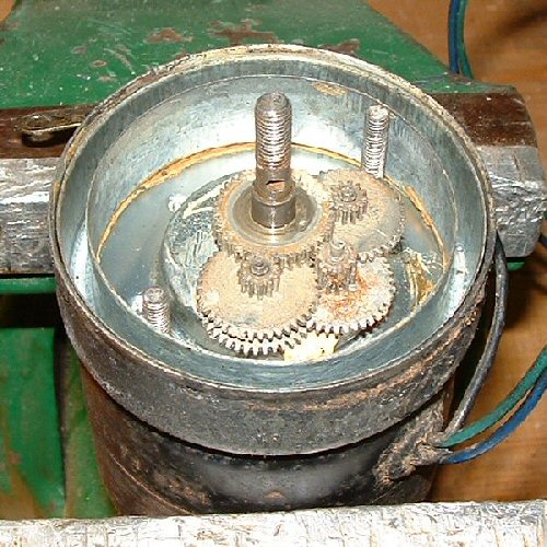
What you are now left with is the reduction gearbox in the middle and the outer winding plenum chamber. The gearbox top cover can easily be lifted out at this stage to reveal the gear set underneath. |
|
|
This whole assembly can now be lifted off the motor, you may need to pry it free carefully, I used a screwdriver. All that's left now is the motor itself. |
|
Remove the motor from the vice. Time for a well earned break... pat yourself on the back and go and make yourself a cuppa! |
|
|
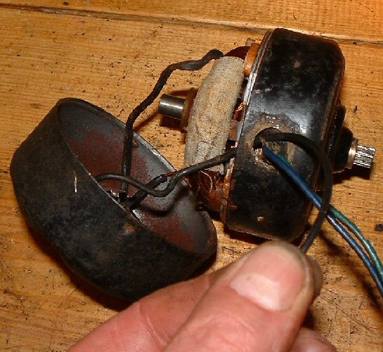
Remove the rubber washers and nuts from the through bolts. The grommet protecting the wires is probably brittle and perished, carefully cut it away so that the earth wire can pass through the hole a little way when the motor casings are separated. Now separate the motor casing halves so that the armature can be removed. |
|
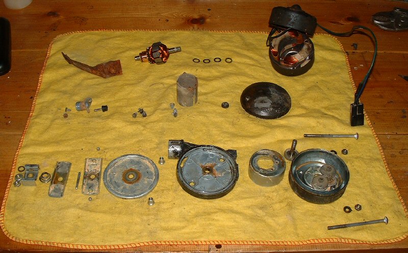
Here are all the components of the dismantled drive assembly laid out neatly on the bench. There are a few jobs that need to be done before the drive unit is re-assembled. |
|
|
|
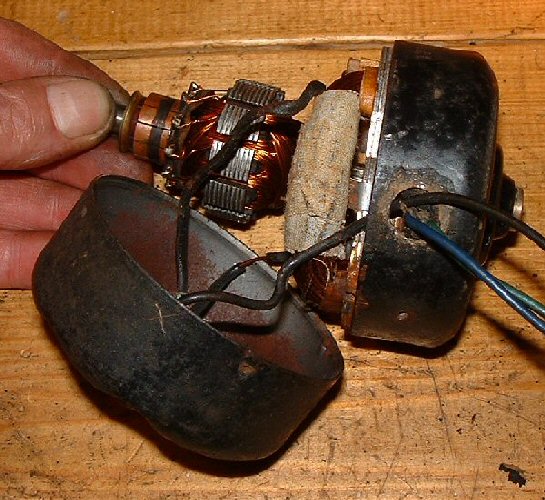
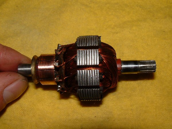
If you're lucky, the armature will be in really good condition, like this one. Carefully undercut the commutator, all that needs to be done is to scrape the old eroded carbon and copper from between the segments of the commutator with a scalpel blade, or something similar, and clean it up with a very fine polishing stick. |
|
|
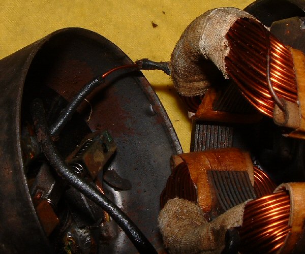
Carefully clean off all that old and hardened grease from the reduction gears and the override clutch that was slowing everything down. Also I noticed some damaged insulation on one of the field wires. The insulation appears to be made of fabric and time has taken its toll. Carefully unsolder the wire, slip on a piece of modern plastic wire insulator and re-solder the wire. |
|
|
|
To reassemble the motor, push the carbon brushes back into their housings against spring tension and secure by pushing a length of copper wire through the small hole in each of the brush housings. This will hold them in place until the commutator is engaged. Grease the shims and replace them on each the armature shaft, or however they were arranged when you dismantled it. Slide the armature into the opened ended part of the motor casing just enough to be able to bring the rear part of the motor casing over the other end of the armature. Now push the armature back just enough to be able to pull the copper wires away and let the brushes snap against the commutator. Push the armature all the way home and bring the two halves of the motor housings together. Assemble the through bolts and secure with the nuts. Do not over tighten and check for free rotation. Now connect the motor to a 12 volt car battery to see how it works. If all has gone well the motor will spin with a surprising degree of torque. Take note which of the two power leads makes the motor turn clockwise - this is the lead that you will need to power up later on to engage the nylon drive cord in the drive unit. Reassemble all of the remaining parts of the drive unit in the reverse order that you dismantled them not forgetting to grease the reduction gears and the override clutch. Power up the drive unit just to make sure everything is working as it should, and install a new grommet to replace the old one that had to be cut off - you will have to cut it to get it on and repair it with some silicone sealant. |
||
|
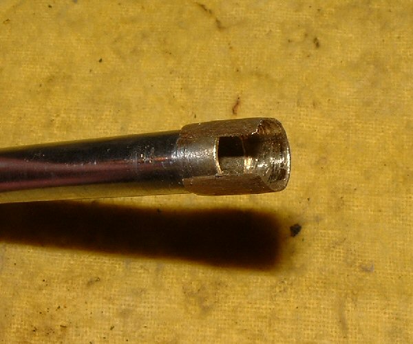
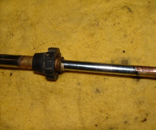
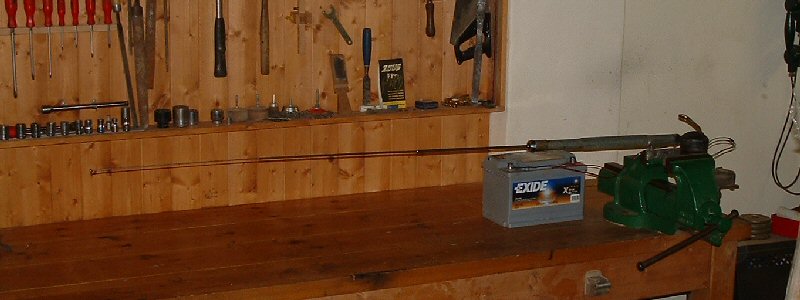
Now for that broken mast. Hold the very top telescopic section with a pair of soft jaw pliers and remove mast tip. Now slide the broken mast section up towards the top and off the end. Remove the lower broken piece by pushing it down and out the bottom of the mast outer section - the mast outer section is the piece that doesn't move, with the the hook up wire and the insulator bushing. The broken ends will be deformed so you will need to carefully cut a short section off each of the affected ends using a hacksaw, clean up the edges and rough up the surface that is going to be soldered. |
|
|
|
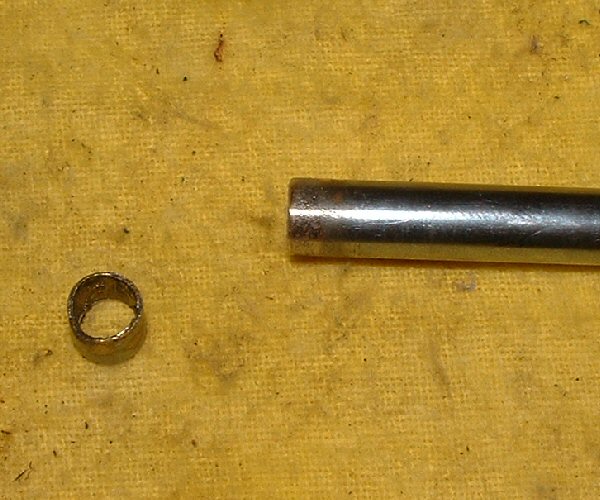
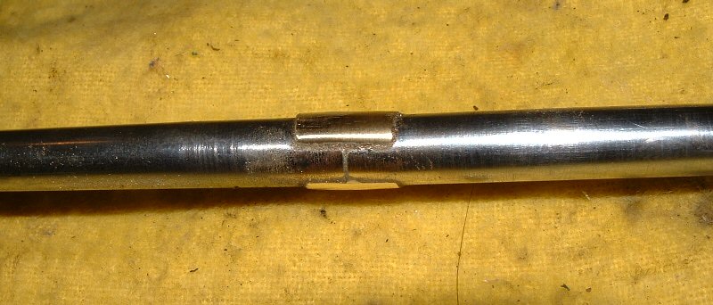
The break in this mast is about 4 inches from the lower end of the lower most telescopic section. The plan is to repair the brake with an external sleeve made from 1/2 an inch of tube removed from one of the trimmed sections. Being an external sleeve means, as the mast is extending, the repaired section will hit the top of its outer mating part and stop only 4 inches before it was designed to do - a small price to pay. Cut the sleeve lengthwise and use the shank of a drill, of the same size as the outer diameter of the mast section, to re-shape it. |
||
|
Reduce the wall thickness using a grinding wheel, slide the sleeve onto the mast section and check that it will fit through the mast outer section easily. |
|
|
Clean the mating areas and apply some flux. Slide the parts together and adjust until everything looks straight then go ahead and solder it. |
|
Clean up the joint and check it again in the mast outer section. |
|
Any solder intruding into the inside must to be removed, otherwise the mating mast section won't slide. Holding the repaired section vertical, I heated the tip of a length of 1/8th inch diameter wire until it was red hot and rattled it about inside. Any bits of unwanted solder simply fell through the open mast section. |
||
|
Slide the mast sections together taking care not to damage the fragile brass fingers near the ends. Screw the mast tip on and start the nylon drive cord into the drive unit. Power up the drive unit, using the power lead that you took note of earlier, and let the nylon cord enter and get started in the drive unit. Just let the nylon cord coil sufficiently for you to manually push the mast assembly insulator bushing into the socket on the drive unit - at this stage the mast will be partially extended. Bring the support tube over the mast assembly and locate it over the drive unit socket taking care to let the hook up wire come through the hole. Re-attach the screws and the earth wire. Before any more assembly takes place, test to see if works. The mast should fully extend (with the exception of a few inches due to the repair) and come to a stop with the sound of the motor increasing in speed for a couple of seconds then going under load for a split second then speeding up and so on. The same override sounds should be heard when the mast is retracted. |
|
|
|
When you're satisfied everything works OK, solder the hook up wire back on and replace the coax flange, the lower spacer and the mounting bracket. Here it is all finished and ready for the car. |
|
| Home | Astronomy | Cadillac | Palms | Photos | Games | Guest Book | Favourites | HTML | Site Map | Search |
| Best viewed at 1024 x 768 screen resolution using Internet Explorer 5.5 and higher or Netscape 6.0 and higher. Last Updated: |