 |
| |
Rebuilding the Bendix power brake unit...
Who knows when it was apart last
|
The Cadillac has been in storage for about eight years and the brake pedal felt stiff -something's stuck! With the engine running, I pushed the pedal hard and felt something give - probably the wheel cylinder pistons... I'll put that on my list of things to do. In the meantime, the next job is to take a look inside the brake booster. There were two different brake power unit/master cylinder options used on all Cadillacs in 1960: Delco Moraine, and Bendix. The type that was fitted at the factory on my car was Bendix. |
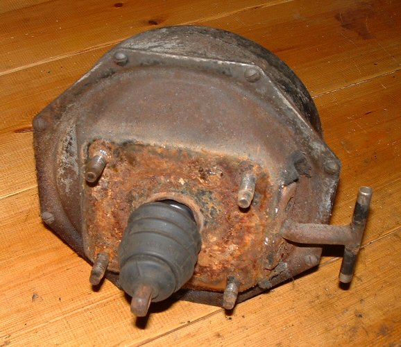
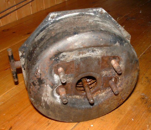
Removing the power brake unit was easy. The master cylinder was already off and all that was needed was to remove the cotter pin and washer at the brake pedal and the four 7/16" nuts on the inside of the firewall. |
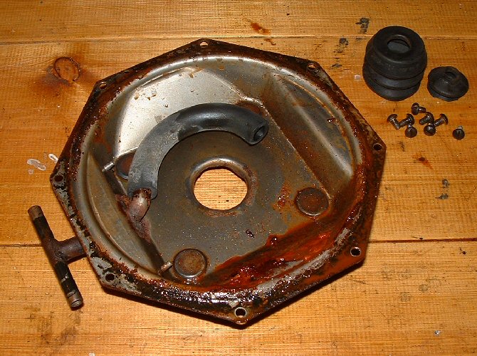
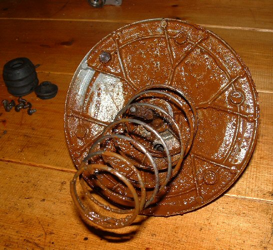
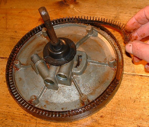
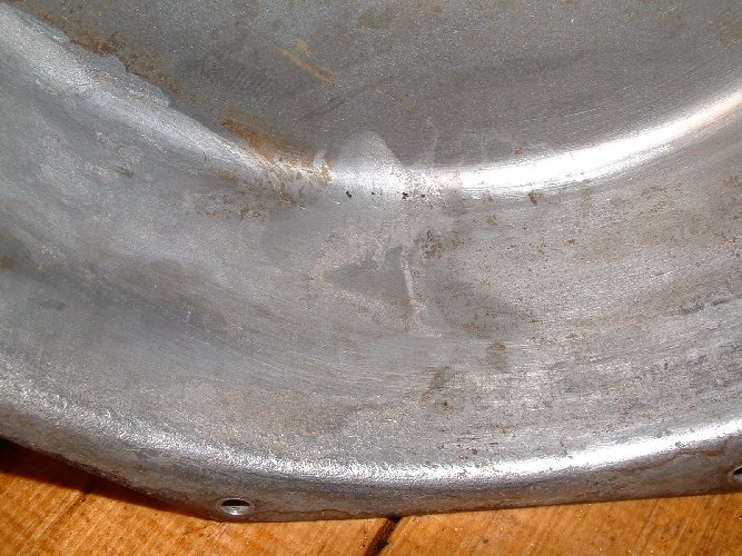
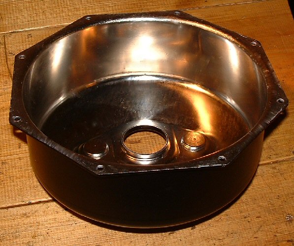
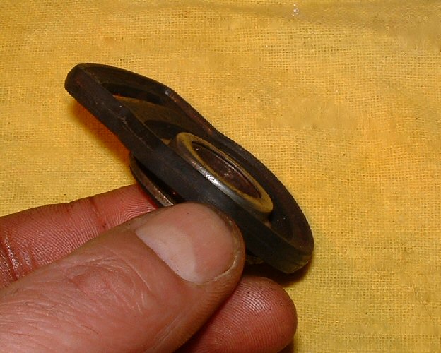
The eight screws, holding the vacuum cylinder to the back plate, were very tight and I'm so glad I own an impact driver. When the cylinder and back plate came apart, approximately a quarter of a pint of rust coloured brake fluid leaked out. I've spared you a picture of the mess it caused! Here is a look inside. |
|
|
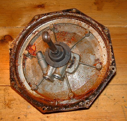
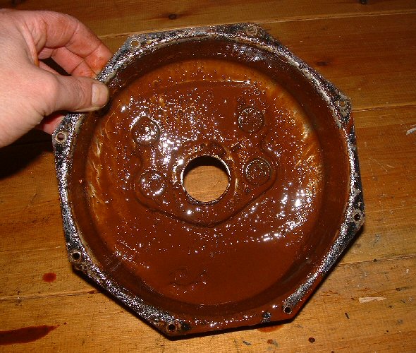
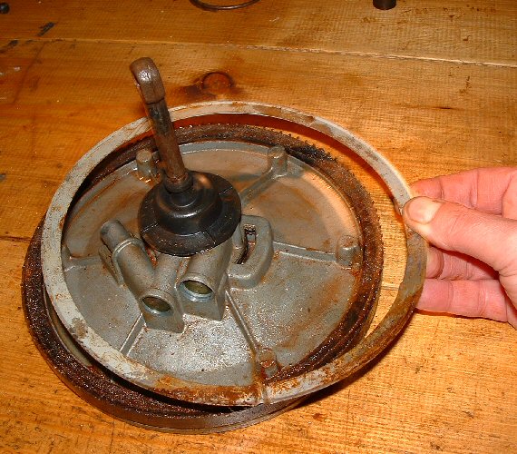
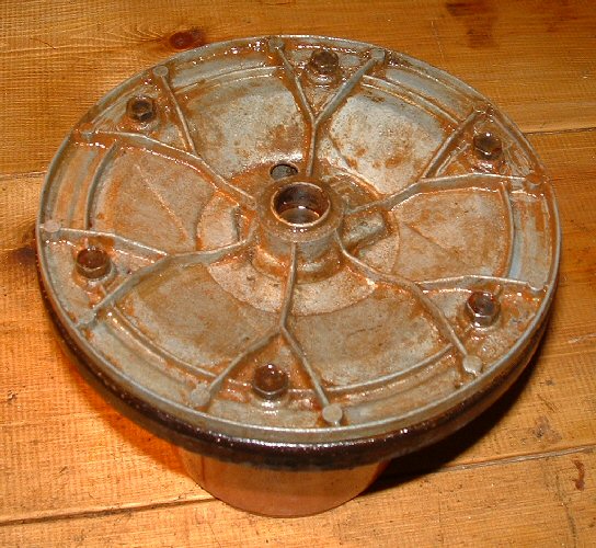
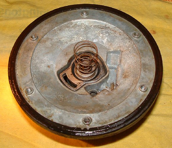
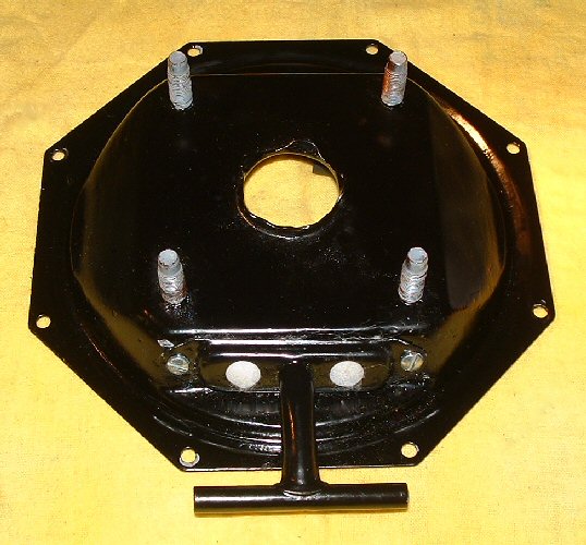
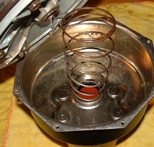
Left is the rear face of the piston assembly before it was removed from the cylinder, centre picture is the front face of the piston assembly with the return spring, and right is the inside of the vacuum cylinder and its unwanted contents. I've no idea when all this brake fluid accumulated inside - but I think some of it must have came through when I pushed the pedal hard earlier on. |
|
|
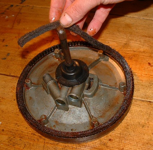
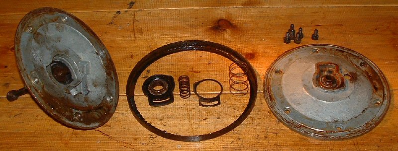
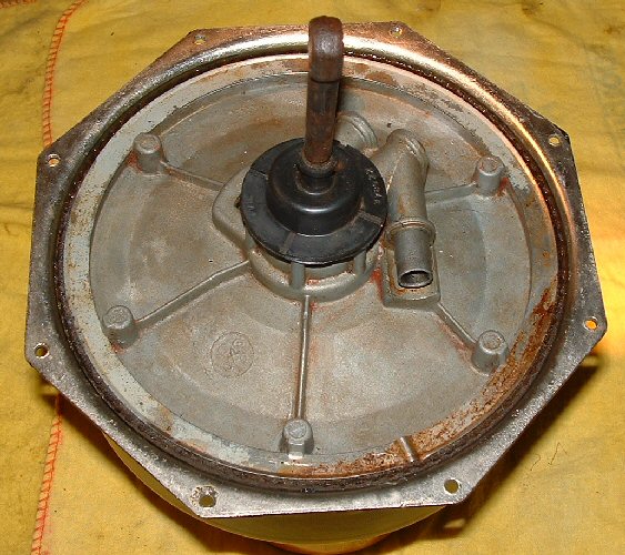
Next lay the return spring to one side and pull out the master cylinder piston push rod. With the vacuum piston laying flat on the bench, remove the felt retaining ring by carefully springing it away from the grooves in the bosses. Then lift out felt seal, and finally the seal expander. Now you have to decide whether or not to dismantle the vacuum piston. Chances are everything is working fine, and if the leather seal looks good (and this one does), you may want to leave it alone. But, with all this mess, I've decided it would be prudent to strip it down and check out the internal parts. |
Leave the valve operating plunger installed and, resting the vacuum piston on a suitable support (I used a plastic flower pot), remove the six screws from the front face of the piston assembly. Carefully seperate the piston halves and remove the leather piston seal, the poppet valve and spring, the diaphragm assembly and the valve return spring. |
|
Now give everything a good clean. Do not use any chemicals on the rubber parts, just gently remove any encrusted rusty residue - the rubber parts in this brake unit were surprisingly supple and unperished. |
|
|
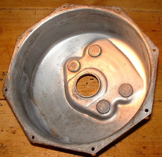
The vacuum cylinder, on the other hand, was corroded inside and was going to need some attention. I checked the manual and discovered that the diameter is stated as nothing more exact than 7 ¾″ and, upon measuring the cylinder, I found it to be 0.020″ oval. I concluded that considering the non exact dimensions of the cylinder, and the flexible nature of the leather piston seal, I could blend all of this corrosion out without spoiling how the piston seals. After sufficient polishing I had the cylinder nickel plated to protect it from future corrosion. |
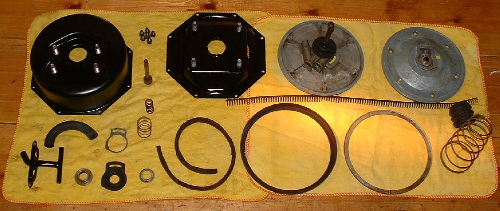
Here are all the components cleaned with all external surfaces painted satin black and ready to assemble. |
Place the rear piston half, rear face down, on the support that was used earlier. Assemble the diaphragm and poppet valve, as shown, and install into the piston together with the poppet support plate, poppet spring and valve return spring. Lubricate the leather piston seal with shock absorber oil and rest, lip down, over the piston half. Make sure no oil gets onto the ruber diaphragm. |
|
Next install the front piston half over the top of the rear piston half, taking care to align the mating parts correctly. Holding the two halves together against spring tension install the six screws loosely. The lip of the leather seal is a little larger than the piston diameter and could settle eccentrically - so you will need to center it. To do this turn the piston assembly the other way up and install the seal expander, the felt and the felt retainer. Soak the felt in shock absorber oil. |
|
Align the leather seal concentrically by eye and turn the assembly the other way up and tighten the screws gradually and in a diametrically opposed fashion. |
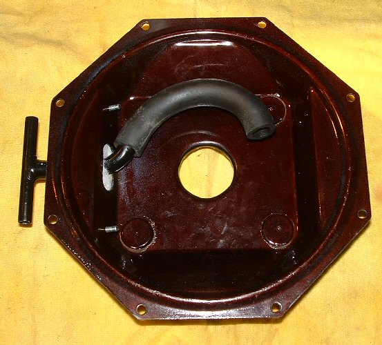
Install the vacuum tee to the cylinder end plate as shown using a new filter. The filter I used was cut from a section of air conditioning filter media that I managed to acquire - looks just like the one that was fitted previously. |
Next postion the piston return spring with the large diameter facing the piston, coat the inside surface of the vacuum cylinder with shock absorber oil and install the vacuum piston assembly. The piston assembly must be aligned so that the internal vacuum hose fits correctly. Ascertain which is the top of the cylinder (the master cylinder mounting studs will give it away) and postion the piston with the vacuum hose connection boss pointing towards the top. |
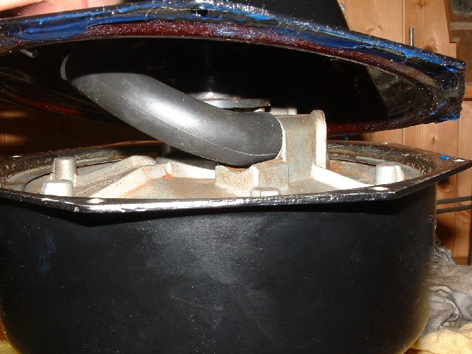
Coat the mating surface of the cylinder flange with a thin layer of gasket cement. Next connect the vacuum hose to the piston assembly and, bringing the cylinder end plate into postion, connect the other end of the hose to the internal part of the vacuum tee. Postion the endplate to the cylinder taking care not to let the hose come off or to let it contact the cylinder wall, install the eight screws tighening diametrically. Replace the dust boot using alcohol to position it and install the push rod. |
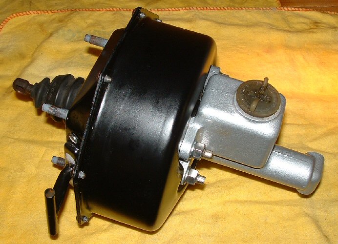
Here it is all finished with the master cylinder installed and ready to fit to the car. |
| Home | Astronomy | Cadillac | Palms | Photos | Games | Guest Book | Favourites | HTML | Site Map | Search |
| Best viewed at 1024 x 768 screen resolution using Internet Explorer 5.5 and higher or Netscape 6.0 and higher. Last Updated: |